We will open the future of Korea's power transmission equipment
We will provide you with the best products and services.
We will open the future of Korea's power transmission equipment
We will provide you with the best products and services.


1. CHARACTERISTIC
1) Parallel
The movement of the grid in the lubricated grooves accommodates parallel misalignment and steel permits full functioning of the grid-groove action in damping out shock and vibration. (Allowed dimensions 2mm~3mm)
2) Angular
Under angular misalignment(2° ~3°), the grid-groove design permits a rocking and sliding action of the lubricated grid and hubs without any loss of power through the resilient grid.
3) End float
Unrestrained end float for both driving and driven members is permitted to the grid slides freely in the lubricated grooves. It can also be limited to any required amount.
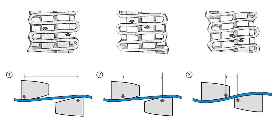
4) Torsional flexibility
Torsional flexibility is the ability of taper grid couplings to torsionally deflect when subjected to normal, shock or vibratory vibratory loads, providing flexible accommodation to changing load conditions.
① Light load
The grid bears near the outer edges of the hub teeth. Thelong span between the points of contact remains free to flex under load variations.
② Normal load
As the load increases, the distance between the supports on the hub teeth is shortened, but a free span still remains to cushion shock loads.
③ Shock load
The coupling is flexible within its rated capacity. Under extreme overloads, the grid bears fully on the hub teeth transmits full load directly..
2. ADVANTAGE
1) When overload, grid is assigned a part of safety pin and prevents breaking of the shaft or machinery part by cutting of grid.
2) When the centering misalignment excessive much, it can protect the relating machine by the virtue of shearing of grid or cover or tooth.
3) The life of all parts (Mechanical seal and bearing, etc….) can extend as a double or more.
4) Repair and check is needed scarcely, it costs short repairing time.
5) Establishment, assembly and maintenance easy by getting rid of center misalignment.
6) It always transmits the power fully(100%) and makesno noise.
7) You can use it continually by changing accessories only.
3. APPLICATION
Connecting the line shaft, we have early used the flange or chain coupling but now using the taper grid coupling we will get many benefits.
1) When we need to prevent the transmission of vibration and shock, etc…..
2) When we need adequate power transmission under line misalignment..
3) When we need adequate power transmission angular misalignment..
4) When we need adequate power transmission under end floating. .
5) When we need to prevent breaking of the machinery parts under over load..
6) When reverse revolution is required..
7) When we need smooth starting.
4. LUBRICATION AND HANDLING
1) Grease lubrication
Pack the spaces between and around the grid. After assemble the covers, fill up grease through the lube plugs.
2) Supplement & replacement
Every three month or 240~250 hours later operating you should supply grease. Every 3 months or 4,000 hours later operating you should replace after get rid of deteriorated grease.
3) Selection of grease
The handling of temperature for grease is from -17~70˚C. You choose grease according to the rpm and circumstance.
4) Recommendation grease
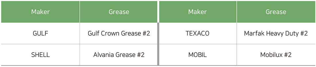
5. STRUCTURE AND MISALIGNMENT CAPACITY
* Misalignment capacity
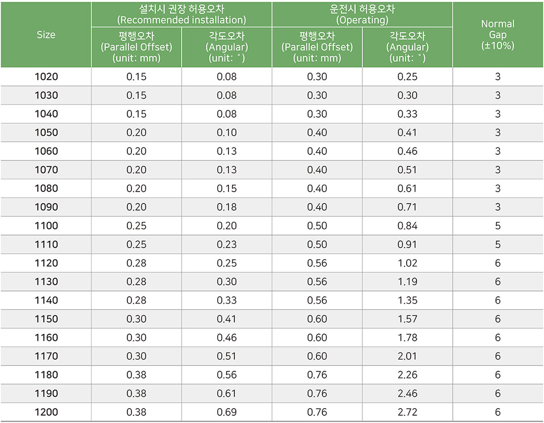
6. Instruction for installation
1) Clean all metal parts using nonflammable solvent. Lightly coat oil seals with grease and place on shaft before mounting hub. Mount hubs on the shafts.

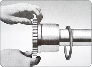
2) Using a spacer bar, make the gap equal in thickness to the normal gap. The difference in maximum measurements must be not exceeded the angular limit.
3) Align so that a straight edge rests squarely on both hubs as shown fig. And also at 90˚interval. The clearance must not exceed the limit specified.
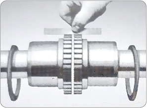
4) After greasing the tooth groove hub, fix the grid in the same direction.
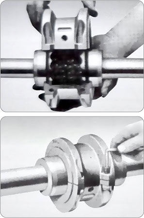
5) Pack the spaces between and around the grid with as much lubricants as possible and position gaskets on half assembled lower cover so that the match marks are on the same side.
7. Selection Method Of Size
1) From the following formula, obtain torque is required for selection.

T = Selected torque (kg·m)
KW = Transmitted load
HP = Transmitted load
N = Working revolution (r.p.m)
S·F = Service Factor
2) First select from comparing with basic torque and find to adopt the same or greater value. And then conclude it’s suitability for application of boring driver.
3) Adopt the minimum rpm when there are common transmitting rpm and also minimum rpm.
4) The load where there are reverse revolution and repetition and irregular operation can double normal condition.
5) Adopt the peak HP, when there are common transmitted power of peak HP in a system
6) Refer to the factory all applications used to lift or transport people. Such as conveyors, cranes, elevators, hoists, lifts or escalators for application of dual load path type couplings and gear drive selections to meet existing safety codes.
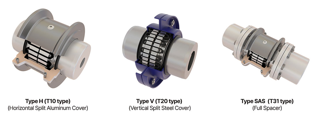
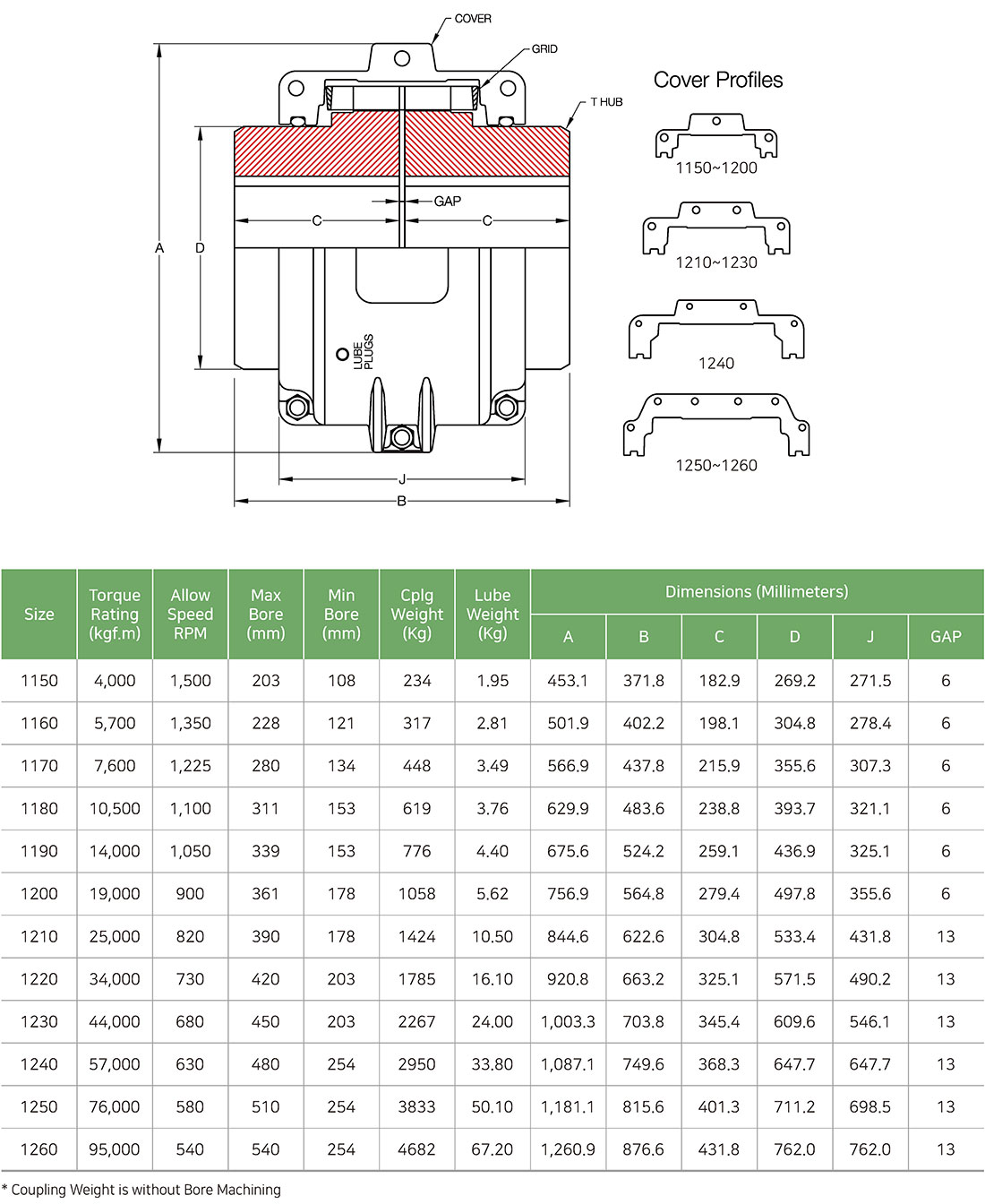
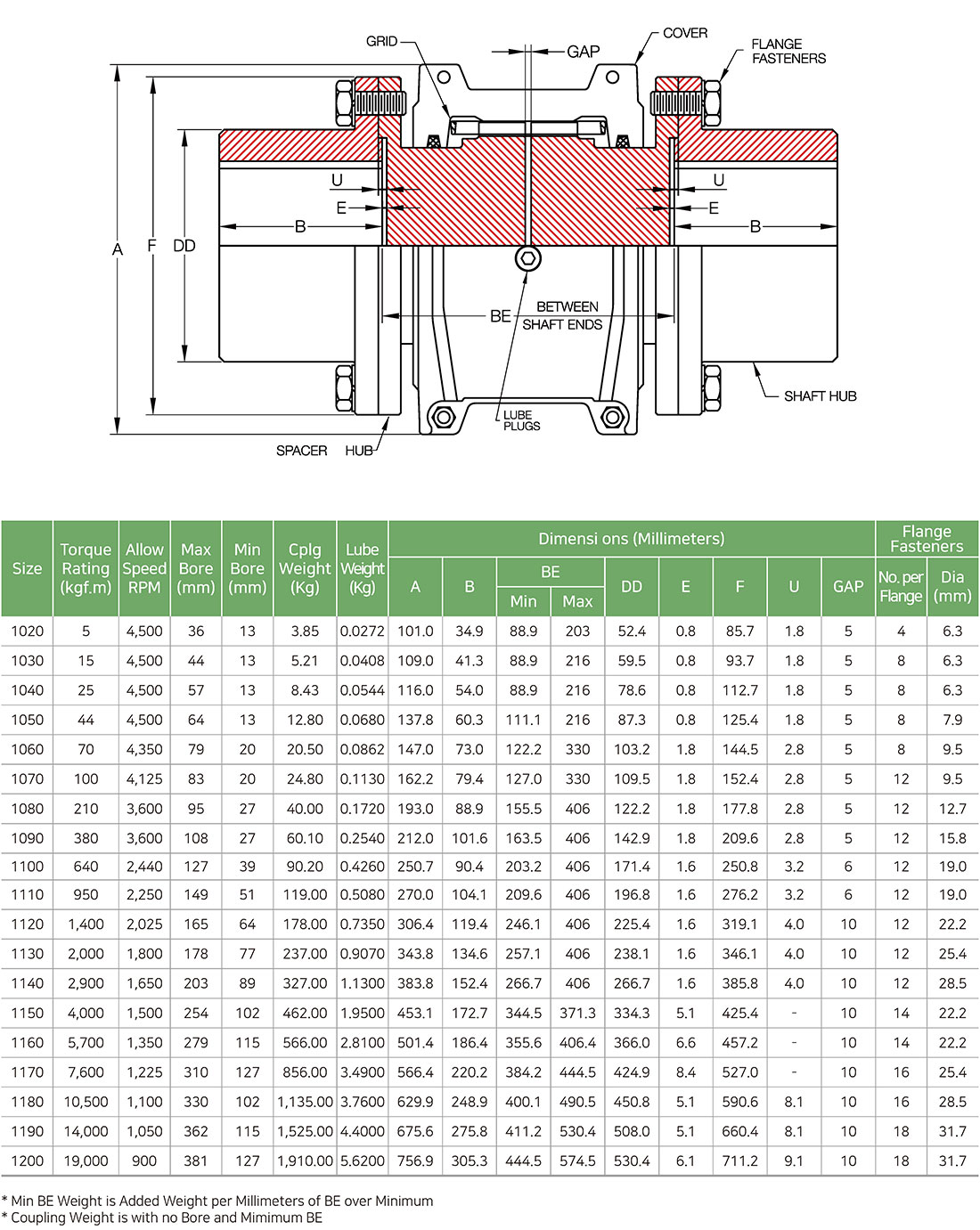
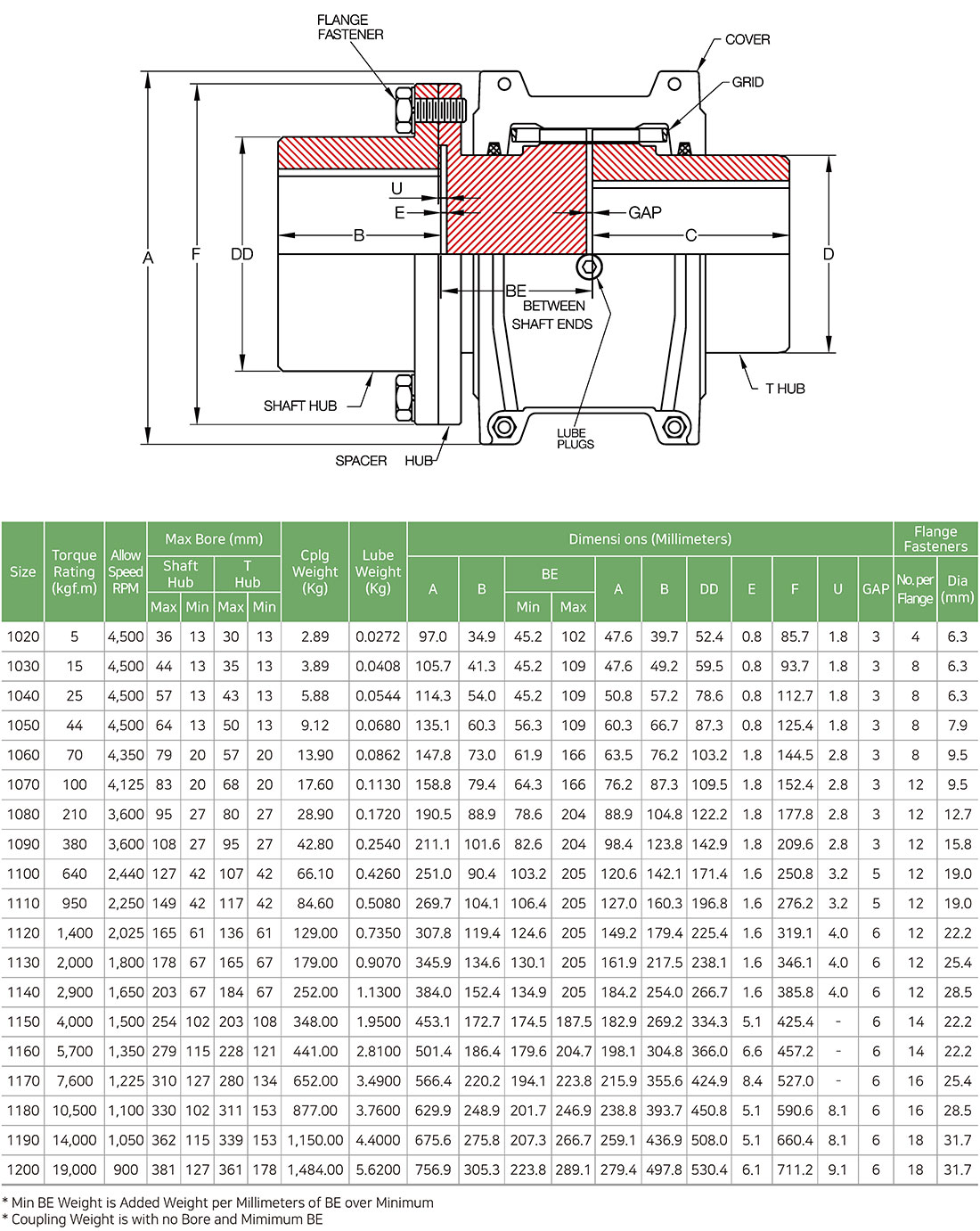
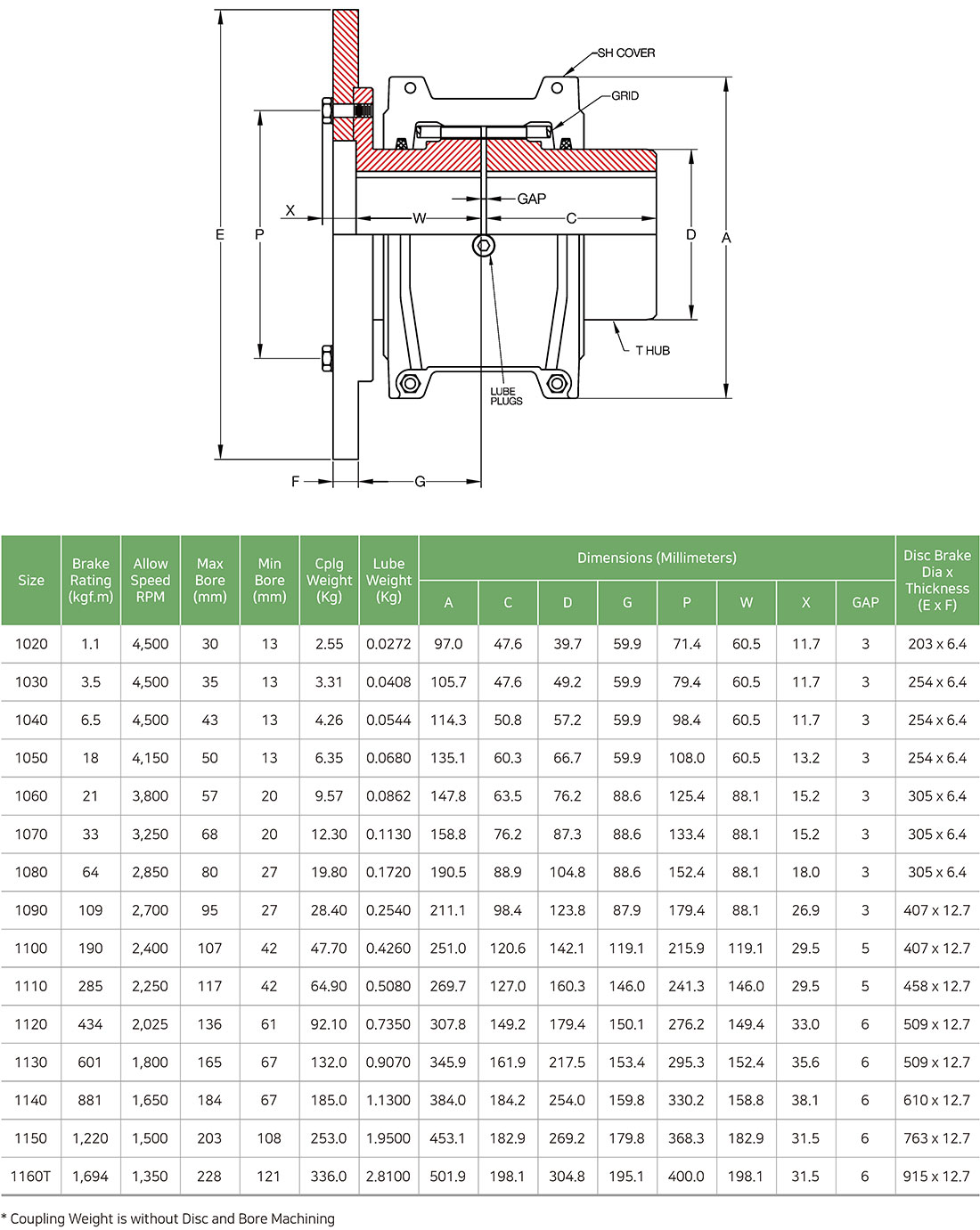
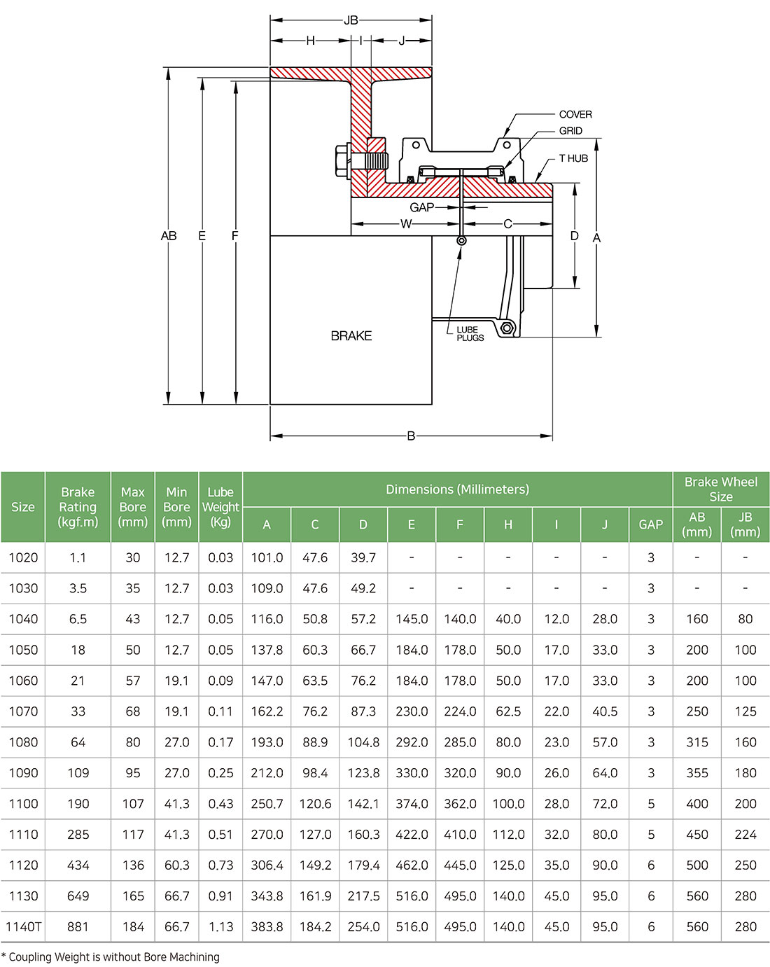
8. DIMENSIONS
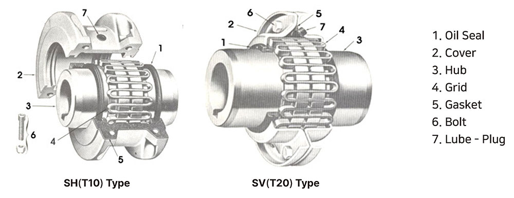
1) H(Horizontal Split Aluminum Cover / T10) Type
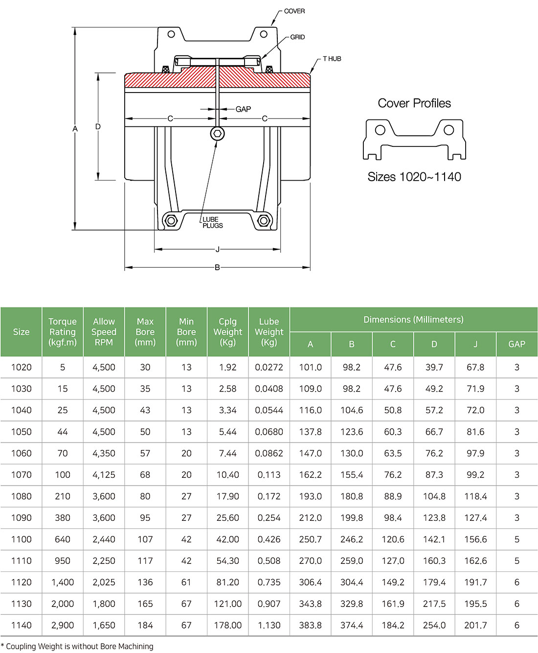
2) H(Horizontal Split Aluminum Cover / T10) Large Type
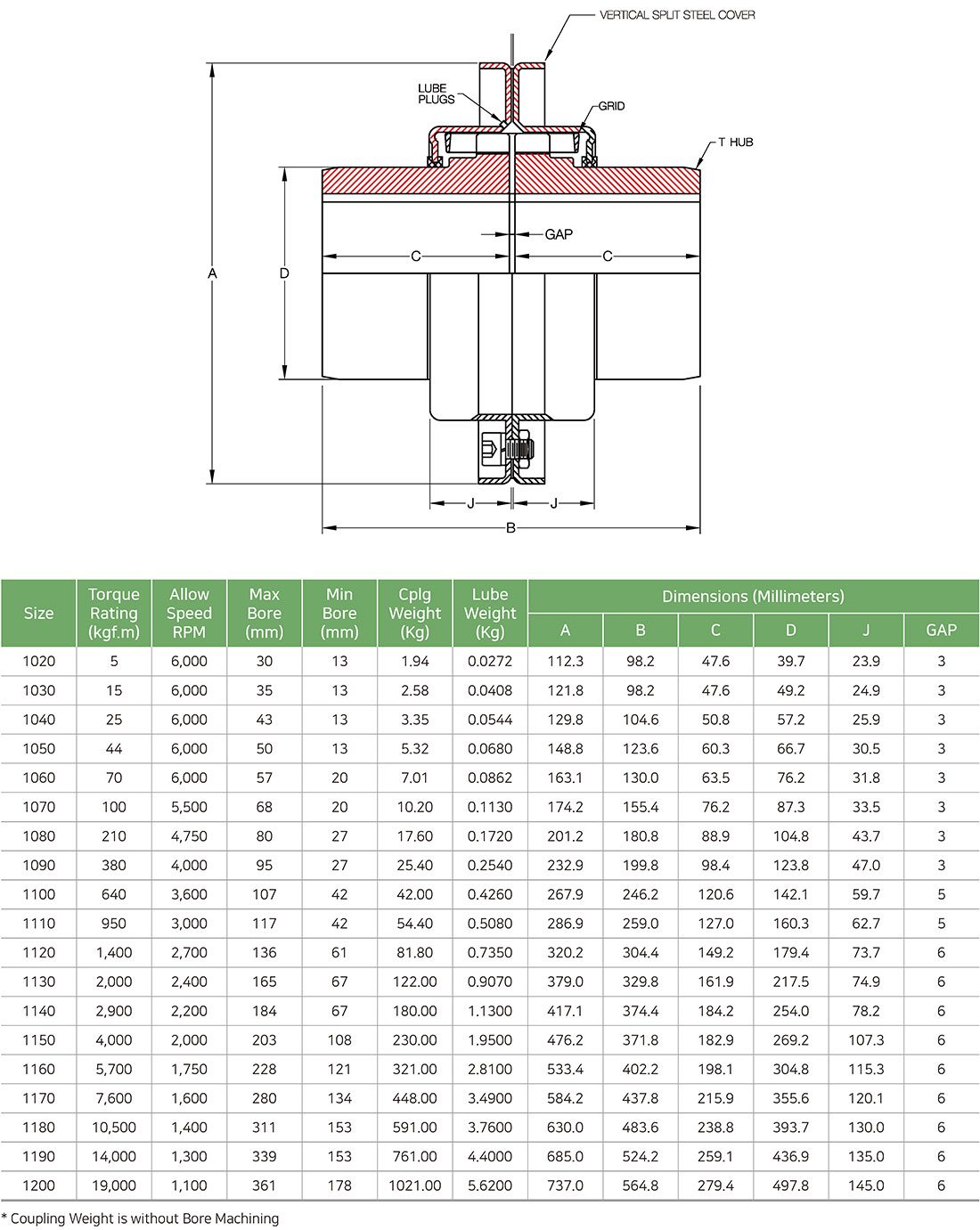
3) V(Vertical Split Steel Cover / T20) Type
4) SAS Type (Full Spacer)
5) SFS Type (Half Spacer)
6) SDB Type (Disk Brake)
7) SBW Type (Break Wheel)
![]()
Copyright © 2024 SEHWAENG Co., Ltd. All rights reserved.