We will open the future of Korea's power transmission equipment
We will provide you with the best products and services.
We will open the future of Korea's power transmission equipment
We will provide you with the best products and services.


1. STRUCTURE
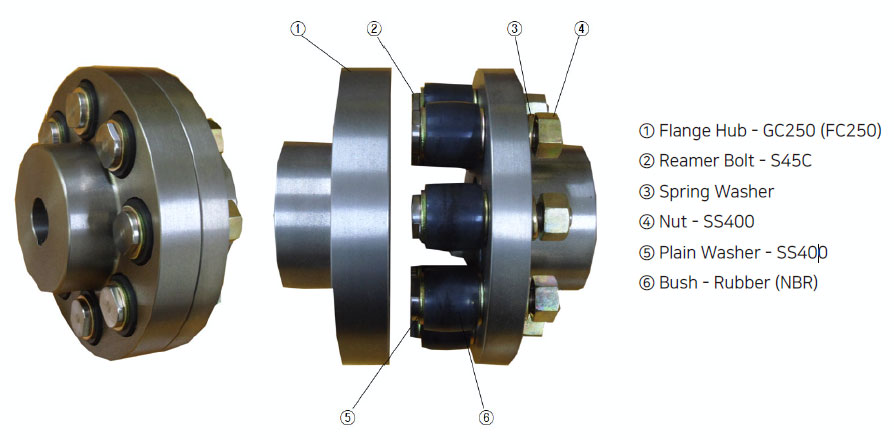
2. CHARACTERISTIC
When connecting the line shaft, flange flexible coupling has many requirements with simple assembly / disassembly and extremely lowest price.
Moreover, Flange flexible coupling is the superior quality products made with modern production facilities and advanced management technique according to KS B 1551/1552(Korean Standard),
it has been enjoyed a good reputation from local line as well as foreign customers.
3. ADVANTAGE
1) Easy and simple installation and disassembly and maintenance.
2) It transmits power smoothly.
3) It has available absorption of shock load and vibration.
4) Need no lubrication, no maintenance.
5) The power to be pressed shaft from coupling does not occur.
6) It can be measure from side as directly connected. It is possible to rotate it as directly connected from outside by hand.
7) It is safely operating without any particular guard cover.
8) Simple construction and completely flexibility.
9) interchangeable coupling.
4. APPLICATION
1) When we need to prevent the transmission of vibration and shock.
2) When we need adequate power transmission under parallel misalignment or angular misalignment or parallel and angular misalignment.
3) When we need adequate power transmission under end floating.
4) When reverse revolution is required.
5) When we need smooth starting.
5. PRINCIPAL USE
Pump, Compressor, Speed change gear, Air blower, Reducer, Hoist, Chemical machine, Conveyor, Crane, Cement mixer, Construction machine, Metal processing machine, Rolling mill, Tractor, Textile machine, Bending machine, Spinning and weaving machinery
6. SELECTION METHOD OF SIZE
1) From the following formula, obtain torque is required for selection.

T = Selected torque (kg·m)
KW = Transmitted load
HP = Transmitted load
N = Working revolution (r.p.m)
S·F = Service Factor
2) First Select from comparing with basic torque, and find to adopt the same or greater value. And then conclude it’s suitability for application of boring driver.
3) Adopt the minimum rpm when there are common transmitting rpm and also minimum rpm.
4) Be careful about the load where there are reverse revolution repetition and irregular operation can be double normal condition.
5) Adopt the peak HP, when there are common transmitted power of peak HP in a system.
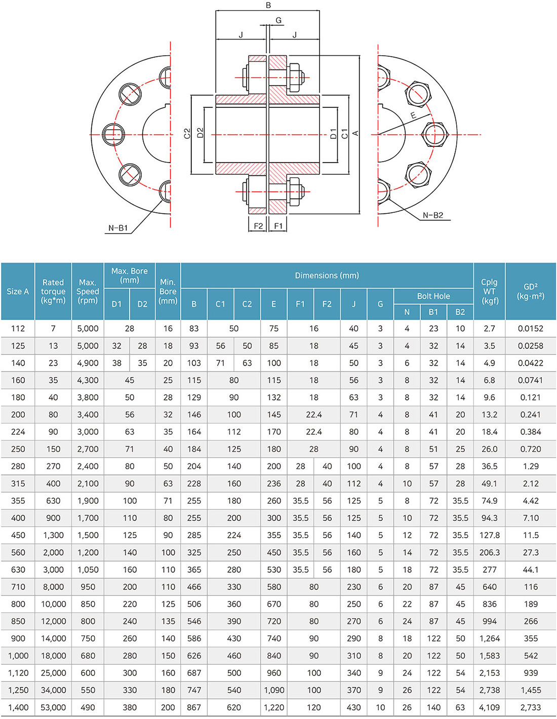
7. DIMENSIONS
1) FFC (FC250) Type
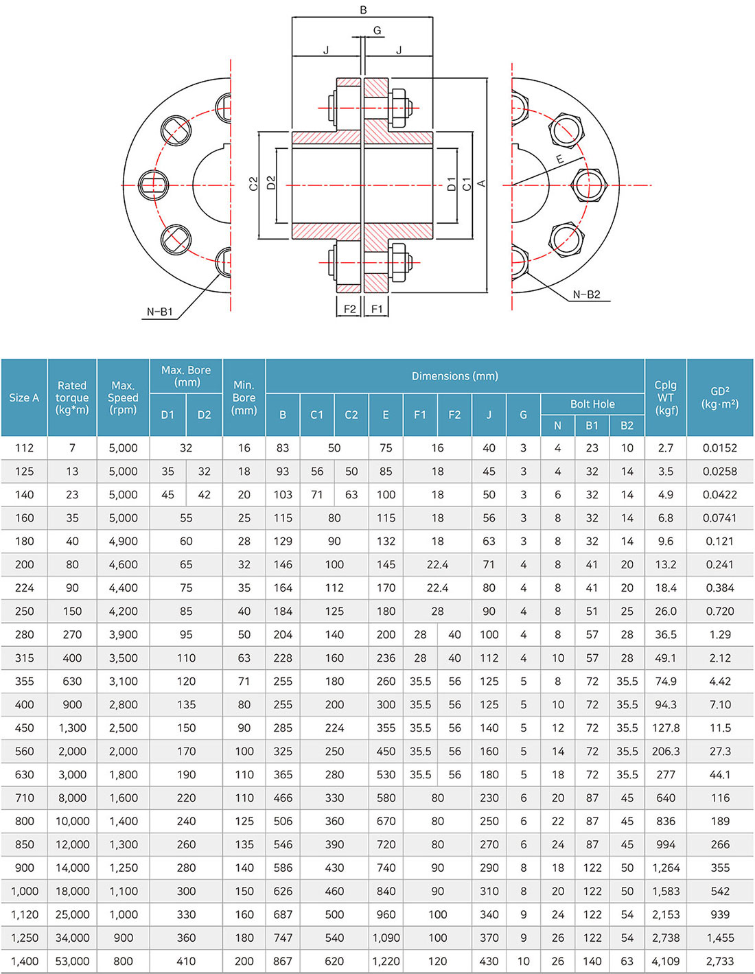
2) FFCH (S45C) Type
3) RFC (FC250) Type

4) SFFC (FC250), SPACE (S45C) Type
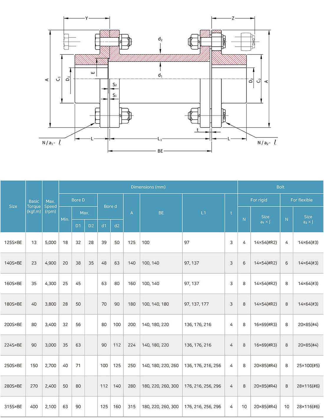
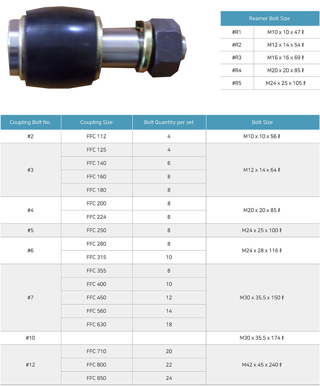
8. COUPLING BOLT
![]()
Copyright © 2024 SEHWAENG Co., Ltd. All rights reserved.